Umair Niaz, Bureau Veritas, UAE, Muhammad Hussain, University of Wollongong, Australia.
The corrosion aggressiveness of soils and other areas has been a topical problem in transmission pipelines (both gas and hazardous liquids). Despite following best practices, corrosion and mechanical failures can still occur during operational, testing, and even construction phases, which may lead to loss of containment. These failures can also be triggered by non-conformances during design, construction,
commissioning, as well as during operation, e.g. by operating beyond the integrity operating window. The actual service life of pipelines is predominantly determined by the rate of metal corrosion. Therefore,
monitoring of the corrosion aggressiveness of soils, then working out the technology needed to reduce and inhibit the development of corrosion processes has always been a reliable method to prolong the service life of pipelines.
This article discusses a case study of the corrosion issues of an aboveground pipeline, caused by the combined effects of underlying soil and environmental factors. At certain locations where the bottom of the pipe was in contact with the soil, lack of a proper inspection management system allowed surface oxidation followed by pitting corrosion to occur.

Case Study
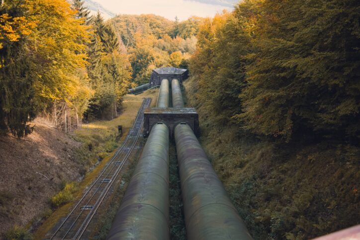
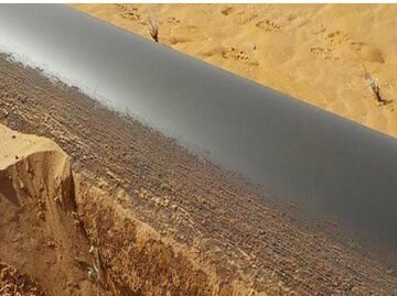
A routine visual inspection of an above-ground pipeline network revealed that at a number of locations external corrosion in the form of general scaling (surface oxidation) and localized pitting was starting to
occur (see photos 1a and 1b). The pipelines were constructed of API 5LC – UNS-S31803, using grade LC65-2205, suitable for Maximum Allowable Operating Pressure (MAOP) of 65 bar and a design temperature between -29 to 90 C. The line was externally coated with 3 Layer High-Density Polyethylene and cathodically protected using an impressed current cathodic protection system. It thus was decided to
further inspect, and then propose recommendations to prevent failures in the future for the damaged/rusted locations.
Considering the actual site conditions of the pipeline sections, a pipeline integrity study was carried out by a multi-discipline engineering team in accordance with ASME B31.8S, “Managing System Integrity for Gas Pipelines”, following the stages below:
• Collection and review of engineering and operating data.
• Review of construction, operating and maintenance history.
• Identification of applicable integrity threats
– Internal corrosion
– External corrosion
– Weather-related and Force Majeure
– Third-party
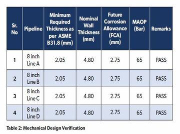
• Evaluation of maximum operating pressure and minimum wall thickness in the most corroded areas as per ASME B31 G.
• Dividing the pipeline into different sections.
• Risk Based Inspection (RBI) study (which included the following):
– Calculation of probability of failure and consequence of failure.
– Risk ranking and calculation of criticality factors based on calculated probability and consequence.
– Development of Inspection Plan for calculated Criticality Factors.
• RBI study using Palladio Software
• Conclusion and recommendations based on an integrity assessment.
Results and discussion
As the risks to the pipeline are not uniform throughout the pipeline system, due partly to geography and geometry (e.g. bends), and partly because of changes in internal conditions, the pipeline was divided into different sections (A, B, C & D).
After reviewing the construction data of the pipeline, it was found that good engineering practices had been followed in accordance with the applicable codes and standards at the time of construction. These pipelines contained natural gas with maximum of 1.14 mol% of CO2 and 3 ppm of H2S. However, in upset conditions there was a chance of water vapour condensation that would produce carbonic acid with the CO2. There was also a provision for portable chemical injection skids (scale inhibitor and wax inhibitor) that could be used in upset conditions for well heads, and other flow lines. DCVG survey reports revealed no coating faults / defects.
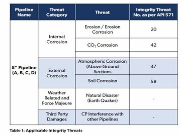
After reviewing the operation history, all the potential integrity threats associated with the pipelines were analysed as per ASME B 31.8 S [1], ASME B 31.8 [2], API 571 [3], and are given in Table 1. The interactive nature of the threats (i.e., more than one threat occurring on a section of the pipeline at the same time) was also considered.
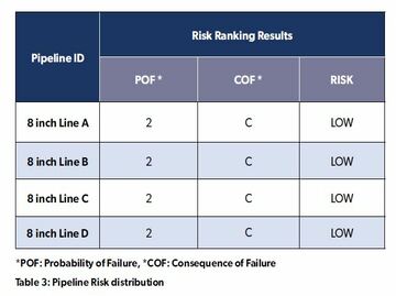
A risk analysis and integrity assessment was carried out by using the Palladio Pipeline Integrity Management System Module and a summary of the risk assessment is given in Table 3. The overall risk for these sections was found to be Low.
The corrosion which was observed on the above-ground pipeline sections can be categorized into the following two types:
• General scaling (surface oxidation)
• Localised areas affected by the presence of chlorides/gypsum and in particular, wetted soil conditions
External corrosion has been recognized as one of the primary mechanisms causing failures of oil/gas transmission pipelines in soil, and potentially causing adverse impact on the environment and communities. Generally, pipelines have a minimum depth of earth cover to reduce the risk of external damage to them, to people, and to nearby properties. Corrosion mostly occurs at coating failures, where the applied cathodic protection (CP) current is shielded from reaching the steel.
Conclusions from the study
• These sections of the pipeline were transporting well fluids (condensate, sweet gas, water) to the Gas Processing Plant. Erosion/ erosion-corrosion was likely to occur in these pipelines as, the well fluids may contain solid particles or liquid droplets.
• Concentration of CO2 in these pipeline sections was found to be a maximum of 1.14 mol %, however the concentration of H2S was found to be 3 ppm (less than 50 ppm limit for safe operation), therefore only
CO2 damage was applicable to these lines.
• There was provision for portable chemical injection skids (scale inhibitor and wax inhibitor) that could be used in upset conditions for wellheads, and other flow lines.
• The pipeline was laid over moisture-containing soil, and part of the pipeline was found to have been buried due to wind. Soil analysis revealed the nature of the soil in close proximity to these sections as highly corrosive. Therefore soil corrosion was very likely to occur. A matrix of the corrosion risk factors High, Medium and Low of soil backfill were analyzed following the guidance in BS EN 16299:2013 diagram [5], and API 651 [6] and shown in Table 4 and Figure 2.
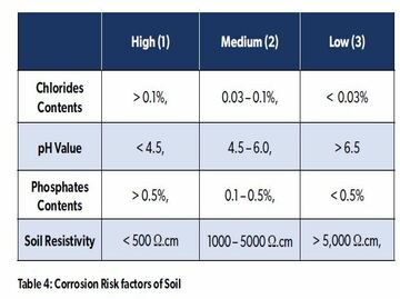
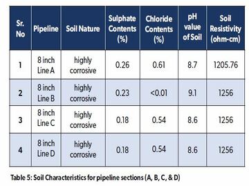
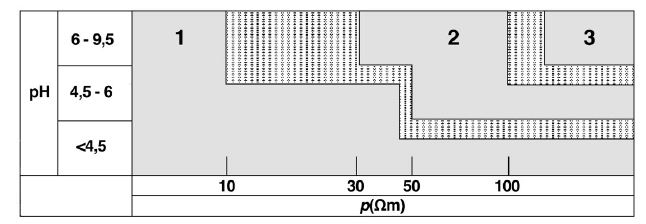
Figure 2
Corrosion Risk factors of Soil, High (1), Medium (2), Low (3)
Recommendations from the study to prevent failures in the future
• Regular recording of CP test posts should be performed in line with cathodic protection procedures.
• Cathodic protection station inspection – monthly check of the DC source (transformer-rectifier), drain point potential measurement, and ground bed resistance.
• Pipe-to-soil potential survey – biannual check of cathodic protection level at all the test point location along the pipeline as per NACE SP0169 [7].
• On/off potential survey – annual check at all the test point location along the pipeline to assess and adjust the true polarised potential.
• Close interval potential (CIP) survey using synchronised current interrupter at all the CP stations influencing the pipeline to be surveyed to assess the pipe-to-soil potential at close interval (1-2 metre) throughout the pipeline route. Inspection interval 3 years or as and when required basis.
• Direct current voltage gradient (DCVG) survey to identify the external coating defects, and to rank /prioritise the severity of the coating defects. Inspection frequency – 3 years or as and when required.
• Interference corrosion survey to identify locations of stray current between multiple pipelines (either belonging to same company or different companies) crossing/sharing the same pipeline right-of-way.
Inspection frequency – 3 years or as and when required.
• Pipeline current mapping survey to identify the magnitude of the current, and depth of the pipeline. Inspection frequency – 3 years or as and when required. This technique is particularly suitable for pipelines suspected with disbonded coating.
• Bell hole (visual) coating inspection survey to check the coating condition and pipe surface. Inspection frequency, as and when required.
• External corrosion direct assessment (ECDA) process to assess and manage the external corrosion threats on the pipeline in line with NACE standard practice SP 0502-2008 (section 10.6.3) [8].
• Effective coating programme should be maintained in order to avoid any kind of external corrosion.
• Internal corrosion direct assessment (ICDA) process to assess and manage the internal corrosion threats on a dry natural gas pipeline in line with NACE standard practice SP 0206-2006 (section 10.6.3) [9].
References
[1] ASME B 31.8, “Managing System Integrity of Gas Pipelines”, 2020.
[2] ASME B 31.8S, “Gas Transmission and Distribution Piping System”, 2021.
[3] API RP 571, “Damage Mechanisms affecting Fixed Equipment’s in the Refining Industry”, 2020
[4] ASME B31G, “Manual for Determining Remaining Strength of Corroded Pipelines”, 2017.
[5] BS EN 16299, “Cathodic Protection of external surfaces of above ground tank bases in contact with soil or foundations”, 2013.
[6] API Standard 651, “Cathodic Protection of Aboveground Storage Tanks”, 2014.
[7] NACE SP 0169, “Control of External Corrosion on Underground or Submerged Metallic Piping Systems”, 2007.
[8] NACE SP 0502, “Pipeline External Corrosion Direct Assessment Methodology”, 2010.
[9] NACE SP 0206, “Pipeline Internal Corrosion Direct Assessment Methodology”, 2016.